PRACTICAL WORKSESSION
- Practical Sessions contain sketches or drawings which must be completed, then uploaded by you.
- This practical drawing must preferably be completed then uploaded after completing the Video WorkSession for the Technical Sketch using Line Geometry. If necessary, review this Video WorkSession again prior to starting this Practical WorkSession
- Upload your drawing using the facility provided below.
- Your uploaded drawing is not automatically graded, however your Educator or Course Instructor will communicate with you if necessary.
- A total of 5 Points will be added to your scoresheet for uploading this Practical exercise.
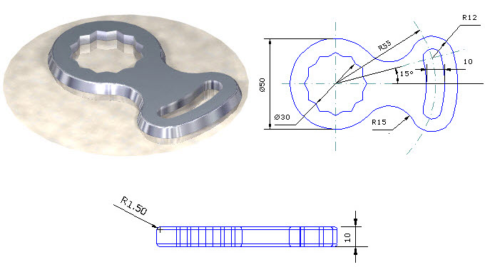
DESIGN BRIEF
- Start this exercise using an appropriate template for 2D design. At least 2 layers are required for the profile and the annotation.
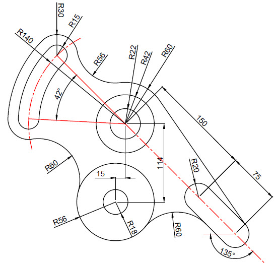
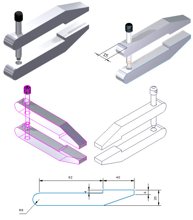
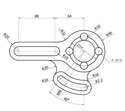
- Draw this sketch after completing the Video WorkSession for the Technical Sketch using Line Geometry, using the methods discussed and demonstrated during the Video WorkSessions.
- Use good design judgement and improvise as accurately as possible for missing dimensions.
- Fully dimension the sketch using all appropriate dimensions.
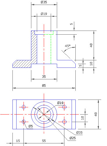
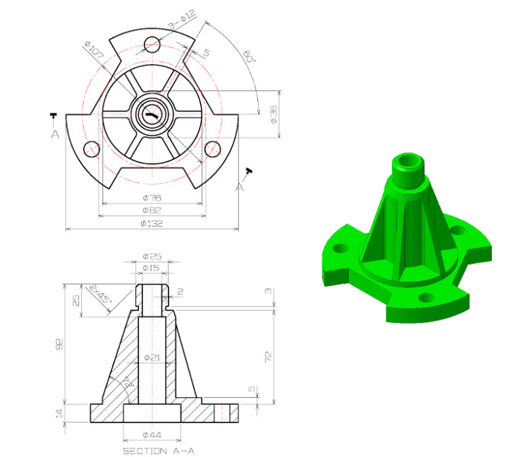
- Insert the hatch pattern, using good judgement to create the correct angle and spacing of the hatch pattern.
- Create a single A3 landscape layout in the Paper workspace, labeling the viewport.
SUPPRORT FOR THIS SESSION