Scenes & Environments
Cubical Maps
Tools > Palettes > Environments > Cubical Maps
Cubical Maps are created from wrapping 6 separate scenes from an image to create a cubical map for an environment.
This can be visualized as each of the 6 images being mapped onto the sides, top and bottom of a cube.
This image is then wrapped onto the scene using the current view as its orientation. For this reason, the background changes in response to a different viewpoint.
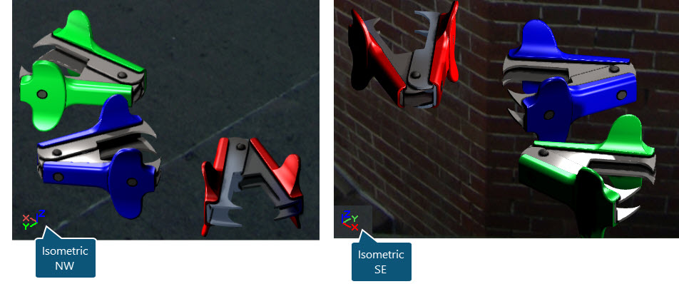
In the examples below , the Cubical Map GoldenGateBridge2 is used.
- In the example below left, the cubical map is orientated to the view which is set to Isometric North West.
- In the example below right , the cubical map is orientated to the view which is set to Isometric South East.
NOTE : Environments are a product of rendering and are only visible when using the render tool.
When using the Environments palette option, the thumbnail can be dragged into the scene to add the environment to the scene. Alternatively, right click onto the thumbnail and select the Set Environment option.
To remove an Environment from the rendered scene, right-click in the Environments palette and select the Set 'None' option.
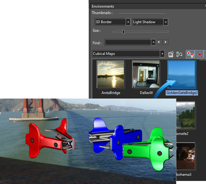
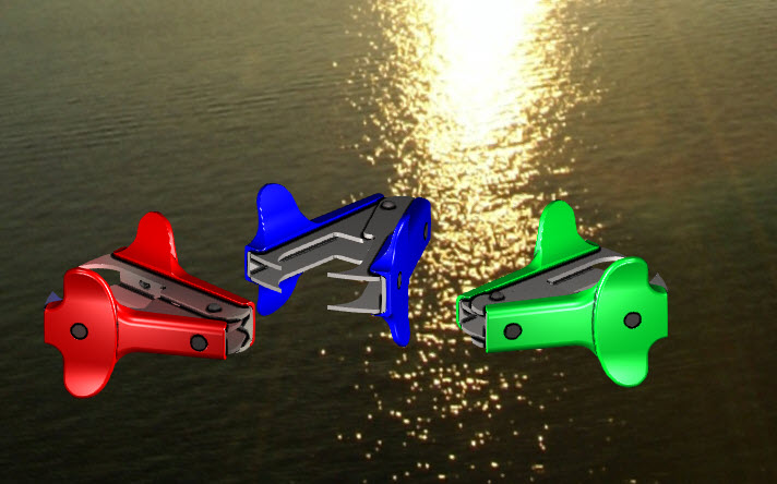
In the example below, the GoldenGateBridge2 option is selected from the Cubical Maps options. The scene was rendered using Draft Render > Visualize > Realistic.
Editing the Cubical Maps ENVIRONMENT
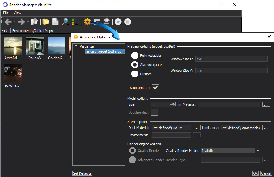
Elements of the Cubical Maps environment can be modified by right-clicking in the Environments > Cubical Maps palette and selecting the Edit Visualize Environments option. This option modifies the overall conditions of the Environment. Double-click onto Options shown below to modify the environment.
Elements of a specific Cubical Maps image can be modified by right-clicking onto the image in the Environments > Cubical Maps palette and selecting the Edit Visualize Environments option. This option modifies the specific Cubical Maps image.
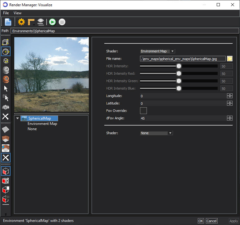
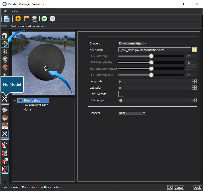
The thumbnail image in the Visualize Render Manager, shown below can be used to rotate the view similar to a 'street view' function. A Cube or Sphere can be used as a substitute to represent the position of the parts in the editor.
Select either cube or sphere in the left vertical menu, then hold down the mouse wheel on the thumbnail to rotate the view. In the example below, the sphere is selected as a substitute for the parts in the editor.
Select the No Model option to remove the sphere or cube.
Click apply to select the preferred orientation. See below to restore the Environment settings and thumbnails.
Restoring the Default Values
The default settings and thumbnails of an environment can be restored by right-clicking into the relevant palette and selecting the Restore Default Environments option from the context menu.
Worked Example
- Download, save to your device and open the Environments drawing.
- Navigate here for more information on using the example drawing for this section.
- Turn the view to any isometric view. Right-click in the editor and select any Isometric view from the context menu. Alternatively, hold down the mouse wheel and move the mouse to rotate the view.
- Select Tools > Palettes > Environments to seat the Environments palette in the editor.
- Select the Cubical Maps category.
- Right-click onto the any thumbnail and select Set Environment from the context menu. In the example below, the cubical map ArstaBridge is used.
- Render the view. Right-click in the editor and select Draft Render from the local menu. The render mode for this scene is set to Visualize > Realistic.
- Hold down the mouse wheel to revolve the scene. The Cubical Map will rotate according to the view.
- To remove the environment, right-click in the Environments palette and select the Set 'None' option
Environments | Cubical Maps
See Also