Compound Objects
Compound objects are formatted from groups or blocks of drawings which are bounded together, usually for easier manipulation in the workspace.
External objects are blocks which are formatted in the current drawing, then output to a common folder for use in other drawings.
All compound objects such as Groups and Blocks are returned to their original parts using the ExplodeDrafting & Annotation | Home | Modify | Explode. feature.
Groups

Drafting & Annotation | Home | Group
A Group is a compound entity comprising a number of separate entities which are grouped together, either temporarily or permanently, for easier manipulation within a drawing.
Groups can only be accessed in the drawing in which they were created.
Groups are informal 'blocks' and are not stored in the Blocks or Symbol Palettes.
The objects which form a Group are restored to their constituent parts by selecting the grouped object after the Group command is issued and using the Explode option.
 Download the sample drawing for this Task.
Example
In this example, outside patio furniture has been drawn and a group will first be created of the objects which form each item, then grouped collectively as 'Patio Furniture'
The patio furniture shown below will be labeled as follows :

Input Group into the command line, then input N to name this group. Input the name Lounger, press enter.
Select the lounger using a window selection, shown below. Press enter.

When the Group Bounding Box option is activated, shown in the illustration below, the newly created Group can now be selected as a compound object, shown below. When selected, its Group information is shown in the Properties palette.

Group selected; Information found in the Properties palette
To identify this object as a Group within the workspace, select the Group Manager feature, shown below.

This will identify the group in the workspace, shown below.

Using the Group Manager
Repeat this by creating Groups out of the remaining patio furniture items, naming each object so the result is similar to the illustration below.

Grouped items named
Each item of patio furniture is now a compound entity, grouped into a named item, shown by the grips in the illustration below. In the illustration below, the Group Bounding Box option is activated.

Compound object grouped, shown by grips
Grouping other grouped items together to create a composite group uses the identical method above. For example, in the illustration below, a new Group Name is created for PatioFurniture and items 1 - 4 are selected.
By using the Group Manager and selecting the PatioFurniture item shown below, the Highlight option can be used to identify the formatted Group, shown below.
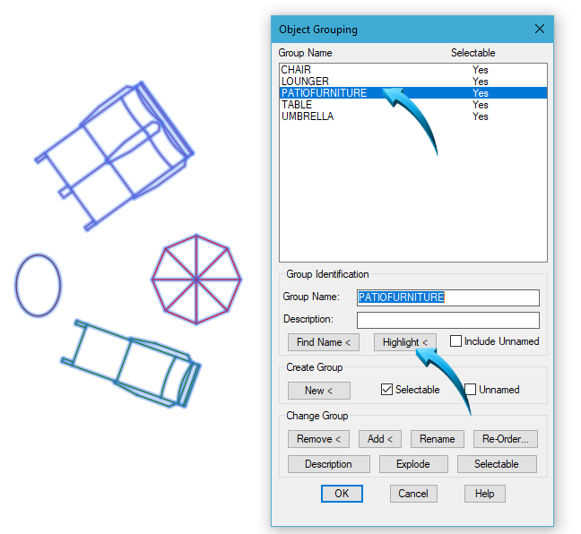
Highlighting the PatioFurniture group
The same method is used to group the newly created groups together into one item called Patio Furniture (no spaces are allowed in group naming).
This collective group can now be selected as a single object, shown in the illustration below. Manipulating this object by means of the Move, Copy, Scale, Rotate and Mirror commands can be done in the normal manner as shown by the illustration below. In this example, the 'grouped object' is being rotated, shown by the pointer.

Group selected as single object & rotated
To return this collective group to its constituent components, ie : Lounger, Umbrella, Chair and Table, select the Group Manager, select the PatioFurniture group and select the Explode option.
The originally grouped objects will remain intact until they themselves are exploded in this manner.
Blocks

A Block is similar in structure to a group, but has more versatile characteristics.
Blocks can contain data called Attributes which help build a database in the drawing.
Blocks can be reduced to their constituent parts using Modify > Explode, but any Attributes attached to such Blocks will lose this information.
Blocks can only be inserted into the drawing in which they were created, but a Block can be shared by writing the Block to an external destination using the Write Block option.
In-place modifications to Blocks can be done using the Block Editor. Such modifications will update all instances of the block in the current drawing.
Create Block

Drafting & Annotation | Insert | Block Definition | Create Block
A Block is created of multiple objects and stored in the resident drawing. In the example below, Part 1-4 are created as Blocks.
Download the sample drawing for this Task.
Example
In the example below, the view is set to an Isometric viewpoint using the ViewCube position shown below.

The assembly is rendered in Conceptual Mode for illustrative clarity during this Task.
Blocks of Parts 1 -3 are created of the parts shown below.

This is done by selecting Insert > Block Definitions > Create New and inputting a Block name., shown by the pointer below. The objects are selected, then stored in the drawing as a Block.
Block Definition
The total number of named blocks in the drawing is shown using Insert > Block Definition > Block Editor. All named Blocks are shown below.

Named Blocks in the workspace
Insert Block

Drawing & Annotation > Insert > Block >
A Block which was created in the current drawing can be inserted into the workspace directly from the Block Insert palette, shown below.

The Block will be inserted into the workspace in alignment with the current viewpoint, shown below. Prior to insertion into the drawing, the block insertion point, scale and rotation angle can be defined. Left click any position in the editor, similar to the position shown below. By default, the Block will be inserted into the workspace using the same scale at which it was created.

Inserting a new Part 1 into the workspace
The inserted block is retained as a compound entity until the Modify > Explode option is used, whereby the block is reduced to its constituent parts. In so doing, all Block information is removed in the workspace only; the Block integrity is still maintained as a stored Block in the drawing and can be re-inserted into the workspace at any stage.
Write Block
Using the WblockShares the Block by writing it to an external drawing file. function allows an block to be shared by other drawings by creating a separate drawing file of the objects. The entire drawing or components of the drawing can be created as a block. Blocks which have been created in the resident drawing can also be saved as an external file using the Write Block option.
Unlike the Block function, the Write Block function creates a physical drawing (dwg) file of the selected objects and this type of block can then be shared and inserted into any drawing.
External drawings which are created using the Wblock function can be used as a 'parts library' and is useful when assembling similar components into a full assembly.
Example
In the example below, Part 1 is saved to a commonly shared drawing folder using the Write Block option. The Block option is selected as the source and the destination file name and path is shown below.

Saving the source Block to an external destination
Inserting an externally stored Block
When a block has been written to an external destination using the Write Block option, this part is reinserted using Insert > Blocks from Library option shown below. This inserts a .dwg file into the editor, allowing the insertion options to be controlled, shown below.

Inserting an external block
The Block Editor
The Blocks Editor provides an authoring palette which allows updating of the selected Block in the workspace.
Parts which are formatted as Blocks can be updated using the Block Editor and all instances of that Block will be modified in the current workspace.
Example
In the example below, Part 3 is modified by adjusting the scale of the part and changing the color.
Select Insert | Block Definition | Block Editor and select Part 3 from the parts list. Part 3 will be isolated in the workspace, using the default Top view viewpoint and the Block Editor palette shown below will be displayed.

Select Modify > Scale and select the part using a selection window. The part in the example below is reduced by .75.
The color properties of the part is changed to yellow. Make sure the ByBlock option is selected in the Properties panel of the ribbon.
To finalize the modification, select Close Block Editor found to the extreme right of the ribbon, saving the changes to the Block.
When the editor is closed, the result is similar to that shown below.
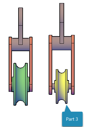
Part 3 updated using the Block Editor