Annotation Tools
Annotation tools provide notational, descriptive or illustrative detail to a drawing in the form of dimensions, hatch patterns, text, leader arrows and revision clouds.
Dimensions
Drafting & Annotation | Annotate | Dimensions

Dimensions are inserted in order to annotateadd notational detail which describes the object a sketch.
Dimensions, by default, are associative. Any changes made to the dimensioned sketch will automatically be updated in the associated dimension.
Standard Orthogonal (Linear, Horizontal and Vertical) Dimensions require a snap mode on the insertion points to ensure accuracy; Radial and Diametric Dimensions require no snaps.
Dimension features are generally standardized upon and saved in a template to ensure consistency and are almost always required to be drawn on a specifically designated layer.
Grips are used to select a dimension and the Properties Palette is used to change any dimension feature.
Dimension Settings
It is recommended that dimension formatting is done in a template which is used for a specific purpose, for example, technical drawing. This ensure consistency between drawings and eliminates the need to reapply standard formats.
Dimension settings are applied by selecting the options arrow shown below.
Accessing dimension settings
The palette shown below will be displayed.

Create and modify dimension settings
Dimension Tools
Dimensions are inserted to annotate an object.
Dimensions are, by default, associative, meaning they will automatically update when their associated objects are modified.
Standard Orthogonal, Parallel and Rotated Dimensions require a snap mode, usually vertex, intersection or center when targeting the insertion points to ensure accuracy.
Radial, Diameter, Quick and Smart Dimensions require no snap modes.
Dimension settings can be pre-formatted by right clicking onto any dimension tool prior to starting the dimensioning task.
Standard dimension settings can be stored in a template for future standardization.
The Style Manager Palette can also be used to create a style of a dimension format.
Some common dimension tools are discussed and demonstrated below.
Dimension text which is modified by removing the angled brackets loses its associativity to the object.
Multiple dimension tools can be accessed by selecting the icon in the menu panel below.

Accessing multiple dimension tools
The sample drawing 11_02 can be used for this task.
Quick Dimensions

Quick Dimensions are used to select multiple objects for dimensioning, regardless of their association to other objects.
In the illustrations below right, the area shown below left was selected. When selecting multiple linear object, such objects should be in the same plane.

Selecting multiple lines for Quick Dimension input
Linear Dimensions

Linear Dimensions are used to create point-to-point dimensions where specific input is required, for example, between 2 parallel points.
In the illustration, below, Linear Dimensions have been inserted using the points indicated by the blue dots.
Linear Dimensions require a snap mode, in this case, the endpoint, to ensure positional accuracy of the insertion points.
Linear Dimensions can also be used to dimension the diameter of a cylindrical object.

Linear dimensions targeting the endpoints of lines
Continue Dimensions
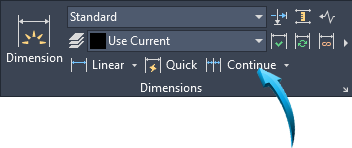
Continue Dimensions are applied by first inserting a 'reference' dimension, shown by the point 1 below left.
Continue Dimensions can then by inserted by selecting the 'reference' dimension, shown by the pointer below left, then indicating the successive points to be dimensioned, shown below right.
It is recommended that an appropriate snap mode, in this case endpoint, be used to indicate the successive points to be dimensioned.
Conditions of dimensioning properties already input into the workspace are modified by selecting the dimensions, then right-clicking and selecting the Properties palette.
To end the Continual dimensioning sequence, right click and select Enter from the context menu.

Referencing the first extension line to 'continue' dimensioning
Baseline Dimensions

Baseline Dimensions are used to dimension objects from a defined edge.
Baseline Dimensions are applied by first inserting a 'reference' dimension, shown below left
Baseline Dimensions can then by inserted by selecting the 'reference' dimension, shown below right, then indicating the successive points to be dimensioned.
It is recommended that an appropriate snap mode, in this case endpoint, be used to indicate the successive points to be dimensioned.
The gap between the dimension lines is applied in the Dimension Style Manager using Lines > Baseline Spacing.
Conditions of dimensioning properties already input into the workspace are modified by selecting the dimensions, then right-clicking and selecting the Properties palette.
To end the Baseline dimensioning sequence, right click and select Enter from the context menu.

Creating Baseline dimensions from the first linear dimension
Angular Dimensions

The Angular Dimension tool dimensions an angled line by selecting the associated line, then the angled line to dimension, shown by points 1 and 2 below. The arc of the dimension is shown placed at point 3 below.

Dimensioning an angled line
The Angular dimensioning tool can also be used to dimension the angle between the end points of an arc, shown below.

Using the Angular dimension tool to dimension an arc
The degree (º) symbol is automatically inserted when using the Angular Dimension tool and no snap modes are required.
The Angular Dimension is an associative dimension; its value is updated when the associated object is modified.
Radius Dimensions, Jogged

Radius Dimensions are used to dimension radial objects such as arcs.
The Radius Dimension is an associative dimension; its value is updated when the associated object is modified.

Inserting a Radius dimension onto the blend
The text of the dimension can either be seated in an aligned position to the dimension line, shown near right, or horizontally. To adjust the alignment of the radial dimension text, use the Dimension Style Manager > Text > Text Alignment > Aligned with Dimension Line.
Radius dimension with a jogged leader, shown below, can be used when dimensioning very large radii where a truncated but jogged dimension is required, shown below right.

Using a jogged radial dimension
The angle of the lines of the jogged dimension can be set using the Dimension Style Manager > Symbols and Arrows > Radius Jog Dimension > Jog Angle.
Diameter Dimensions

Diameter Dimensions are used to dimension circular objects such as circles.
The Diameter Dimension is an associative dimension; its value is updated when the associated object is modified.
The text of the dimension can either be seated in an aligned position to the dimension line, shown below, or horizontally. To adjust the alignment of the radial dimension text, use the Dimension Style Manager > Text > Text Alignment > Aligned with Dimension Line.

Inserting a Diameter dimension
Diameter Dimension using a Linear Dimension
Diameter dimensions can be represented by an linear dimension, shown below.
A Linear dimension is used to dimension between points 1 and 2. Prior to placing the extension line at point 3, the instruction T is input into the Command line. The text %%c45 can be input into the Command line, then the extension line can be placed at point 3.

Inserting a linear dimension as a diameter
To modify a dimension already placed in the workspace, input DDEDIT into the command line to edit the dimension text. Select the linear dimension text, then from the Text Editor Insert ribbon, select Symbol. Select the diameter option.
Dimension Modification
Modifying the dimensional features (physical properties such as color, layer etc) and the geometric measurement info can be done using the Properties palette or the Quick Properties tool.
The position of the dimension can be done using Grips. This allows each node of the dimension, including the position of the text to be adjusted.
Dimensional text can be modified using the Text Override option in the Properties palette, however, dimension text which is modified in this manner removes its associativity to the object. This means the dimensional text will not be updated when the object is modified.
Two methods of dimensional modification are recommended :
- The Dimension Style Manager, and
- The Properties palette.
The sample drawing 11_02 can be used for this task. Make sure the Show All option is activated in the Geometric and Dimension Constraints menu.
Positional
Grips are used to modify the position of any dimension feature, including the text position.
In the example below , the node attached to the text is selected and the context menu is accessed by right-clicking in the workspace. The move text only option is selected.

The dimensional text is relocated to the position shown below.
Take Note
Activated Object Snap Modes may restrict the movement of the text. Deactivate Object Snap settings in the Status bar when necessary.

Dimension Text
The text of the dimension can be modified, however this will remove its associativity to the object.
The text measurement of the dimension can be modified by left-clicking directly onto the text and inputting the required text into the input field, shown below.

Selecting the dimension's text to update the measurement
The Properties palette is also used to modify the text of a dimension, or the command DDEDIT can be input into the command line.
In the example, below, the dimension is selected the Properties Select the dimension, right-click in the workspace, select Properties.palette is used to modify the dimension text using the Text Override options, shown by the pointer.
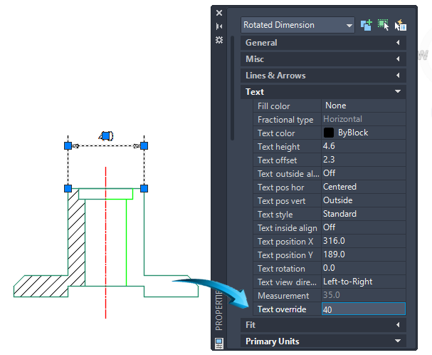
Using the Properties Palette to modify or override the dimension text
Features
All dimension features and settings can be adjusted using the Properties palette.
In the example below, the radius dimension text has been changed from an aligned position to horizontal using the Dimension Style manager shown by the pointer below. To update the text alignment, first select the dimension, then select the Dimension Styles Manager shown by the pointer below. Select Modify > Text > Text Alignment > Horizontal.

Adjusting the dimension text from an aligned position shown above left, to a horizontal position shown above right
Center Marks & centerlines

Drafting & Annotation | Annotate | Centerlines
The Center Mark feature inserts center lines onto a circle or arc.
The Centerline feature inserts center lines onto a polygonal shape constructed of lines.
In the example below, a center mark is inserted onto the circle; centerlines are inserted onto the rectangle by selecting the 2 sets of parallel lines.

Inserting Center Marks & Centerlines
The physical and geometric properties of Center Marks and Centerlines are modified using the Properties palette. In the example below, the Center Mark of the circle is selected to attach grips and the extension beyond the edge of the circle is adjusted to 20.

Adjusting the extension of the Center Mark
Tolerances
Dimensional tolerances are used to indicate the allowable upper and lower deviation, such as actual, maximum etc from the basic dimensional size.
Tolerance values can be appended to the dimension similar to the illustration below right or be displayed appended as limits, shown below left.
The Dimension Style Manager is used to format new and update existing dimensions to create tolerances.
Example
Select the dimension settings page shown by the point below, the select Modify > Tolerances to input the type of tolerance unit required.
Insert a horizontal dimension with tolerances, shown below.

Select the new dimension, then right click in the workspace and select the Properties palette. Input the modifications into the Tolerances panel, similar to those shown below.

Tolerances changed in the Properties palette
Using the Text Editor to insert special symbols
DDEDIT
The dimension text editor can be activated by inputting DDEDIT into the command line.
By clicking onto the dimension text, the text can either be modified or special symbols such as diameter, degrees can be input.
Example
Input DDEDIT into the command line, then select the text of the dimension shown in the illustration below.

Inserting a special symbol into the dimension text
From the Text Edit > Insert menu select the Symbol feature shown below then select the Diameter symbol from the drop-down shown below right.

Leader Arrows

Drafting & Annotation | Home | Annotate | Leaders
Leader arrows are used to annotate a feature that requires a dimensional arrow, but descriptive text.
Leader arrows can be produced as line segments or as curves. To produce a curved leader arrow, check the Draw as Spline option in the Advanced features to the Leader Arrow settings.
In the illustration below, a leader arrow has been inserted using a single segmented line with an angle of the text definition line set to 180º ; the arrowhead is set to 'Dot'; the font is set to AR-CENA.

Text
Drafting & Annotation | Annotate | Text
Text is used descriptively to annotate a sketch or model. Text is also used to label viewports in the paper space layout.
Text is inserted into the workspace by justifying the Left, Center or Right position.
A height and rotation angle is input into the command line or the dynamic Input Fields
Multiple lines of text can be input by using SHIFT ENTER at the end of each line.
The text string and properties can be modified using the Properties palette.
Single & Multiline Text - Input
Drafting & Annotation | Annotate | Text
Similar to dimensions and hatching, text should be inserted onto a layer specifically created for this purpose.
When inserting text, the justification (left, center, right etc) or style (font name, font style etc) can be defined prior to input. Additionally, text height and angle can be defined prior to input.
All text can be modified using the Properties palette and the grips are used to reposition text in the graphics editor.
When inserting Single or Multiline Text, a placeholder, shown below is used as a reference.
Single Line Text - Input

Example
Start the Single Line Text tool from the menu shown above.
At the prompt > Specify start position of text, left click a point in the workspace
Input the required height and angle into the command line or the dynamic input fields.
Type the single line of text, similar the illustration below.

Text placeholder showing left-orientated text
Press Enter once to complete the line. Press Enter again to complete the text string completely.
Multiline Text - Input
Multiple lines of text can be input using the same method as used for Single Line text input. By using the enter key at the end of the line, a new line is automatically started.
Formatting such as justification etc will only be displayed when the text string is finished. This is done by pressing enter twice at the end of the text string, shown by the pointer below.

Placeholder used to input several lines of Single Line Text
Take Note :
Although the text below is input as a single string, the lines of text are selected separately, shown below. Changes to the text string and the text properties (color, layer, etc) are done by selecting the line of text and right-clicking in the editor and selecting either Properties or Quick Properties.

Text Modification - Single & Multiline
Add, Remove or Edit Words and Characters
Single Line text, whether containing one line or several can be modified by double clicking onto the text string. The text placeholder allows inline editing of the text, including adding or removing characters.
In the illustration below, a word is added by double clicking directly onto the text string. The Text placeholder can then be used to add, remove or edit the selected word.

The result is shown below.

Take Note
The Properties palette is used to change any physical characteristic of the text, including the text string. Select the text to change, then right-click in the workspace and select Properties.
Location
The physical location of text can be changed by selecting the text to move, then using the grip handle to relocate the text position, shown below.

Modifying Text Properties
The properties of the text string, such as layer, height angle etc can be modified using the Properties palette. Grips are used to select the single line, then all properties, including the words in the text string can be updated.
In the example below, the text properties are changed using the Properties palette. First use grips to select the text string, then use View > Properties to display the Properties palette.
In the illustration below, the following changes have been done to the text selected by the grips :
- the text color has been changed to blue,
- the text height has been changed

Using the Properties palette to modify text
Multiline Text - Input

Drafting & Annotation | Annotate | Text
Multi Text allows for pre-formatted single or multiple lines of text to be input using a placeholder, shown below. The placeholder is defined by using a window selection to define the general area of input, shown by points 1 and 2 below.

This placeholder can be stretched to widen or shrink the paragraph margins, shown by the pointer in the illustration below.

Changing the shape of the text input field
Text Modification - Multiline
When text is input using the Multiline text tool, all lines of the text form a 'string'. This means that the entire paragraph can be edited using the Text EditorDouble-click onto text. Text Editor menu panel is automatically displayed in the Ribbon..
All Multiline text can be repositioned in theworkspace using grips and the Properties palette can be used to update properties such as those discussed and demonstrated for Single Line text modification above.
Multiline text editing is done by either double clicking onto the text string, or by inputting MTEDIT into the command line or dynamic input fields.
When the Multiline Text tool is activated, the Text Editor menu automatically provides options for formatting the paragraph, allowing specific style formatting. Paragraph characters such as bullets and line spacing can be formatted, in addition to inserting symbols such as degrees (°), plus minus (±) and basic engineering symbols.
Columns within the text can be arranged and spell checks can be performed within the selected text.
The Multiline placeholder is used to correct syntax. Double click to select the text string, then use the editor tools in the placeholder to highlight and replace text, shown below.

Modifying text within the placeholder
Dynamic Columns
The multitext placeholder can be formatted so that columns of text can be arranged when more horizontal space is available than vertical.
In the illustration below, text has been input using the Multiline text with no columns.

Single column text
In the illustration below, the text editor is used to insert dynamic columns which respond to the positioning of the horizontal placeholder. This is done by selecting Insert > Columns > Dynamic Columns > Manual Height option from the Text Editor, shown below.

Selecting the Columns options to divide a chunk of text
In so doing, the text is divided into 2 columns by dynamically stretching the column placeholder, shown below.

Controlling the 'gutter' space of the columns
Take Note
The command MTEDIT can also be input into the command line or the dynamic input fields to access the Text Editor.
Hatch

Drawing & Annotation | Draw | Hatch
A hatch pattern is used to fill a 2D closed boundary, to show distinguishing features, such as concrete etc. Such boundaries are hatched using the Pick Points option.
Hatch patterns are created by ‘filling’ objects, or by defining a common boundary between 2 intersecting shapes.
Areas to be hatched must be closed or be defined by an intersecting boundary.
Hatch patterns are associative when required. The hatched area updates in relation to modifications performed on its associated object.
In the illustrations below, 3 separate boundaries are defined by the intersecting regions.
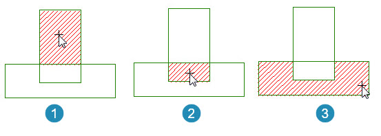
Independent regions identified
Hatch Patterns - Inserting

Drawing & Annotation | Draw | Hatch | Pattern
Hatch patterns are defined by selecting the appropriate pattern and defining an angle and scale relevant to the size of the sketch.
In the illustration below, the hatch pattern ANSI 31 has been selected for pattern 1. The angle is set to 0 (default) and the size is set to 2.
In the illustration below, the hatch pattern ANSI 31 has been selected for pattern 2. The angle is set to 180 and the size is set to 1.

Hatch pattern ANSI 31 with different scale and angle
Hatch Pattern as a Solid Background
In the example below, a solid pattern is selected to create an opaque filling in the hatched area.

Creating a solid hatch pattern
Hatch Pattern Modification
Drawing & Annotation | Draw | Hatch | Pattern
The properties of all hatch patterns are modified and updated using the Properties palette. Grips are used to select the hatch pattern to be modified and such changes are done in the Properties palette.
In the example below, the Properties palette is used to change the color and size of the pattern in object 2. Use the grips to select the pattern, then right-click in the workspace and select Properties from the context menu.

Using the Properties palette to modify an inserted hatch pattern
Hatch Pattern Associativity
All hatch patters, on insertion are created associatively. This means the pattern will correspondingly update when its associated object is updated.
When hatch patterns are explodedReduced to their composite parts using Drafting & Annotation > Home > Modify > Explode however, their associativity to their source object is removed.
In the example below, it can be observed how the hatch pattern in area 2 resizes to fit the newly modified base. In this example, the base was stretched downwards using Drafting & Annotation > Home > Modify > Stretch.

Associatative hatch pattern shown when base is resized
Hatch Pattern - Match Properties
An inserted hatch pattern can be changed so that it is updated to match the hatch pattern properties from another inserted hatch pattern.
In the example below, the Match Properties Drafting & Annotation> Home>Properties>Match Properties tool is used to match the properties of hatch area 2 to match the properties of hatch area 1.

Matching the properties of hatch area 3 to hatch area 1
Hatch Pattern Types
Drawing & Annotation | Draw | Hatch | Pattern
Hatch patterns are inserted to provide annotational, sectional or illustrative detail to areas defined by a boundary.
Hatch patterns can either be solid, patterned or filled with a transitional color sequence know as a gradient hatch. The typical hatch pattern types are illustrated below.
In the example below, a Solid hatch is used to fill the region.

In the example below, the hatch pattern AR-B816C is used to fill the region.

In the example below, a Gradient hatch pattern is used to fill the region.

In all instances above, the scale, angle color and degree of transparency of the hatch pattern is set in the Hatch Properties panel, shown below. This is found using Drafting & Annotation > Annotate > Hatch > Properties, shown below.

Applying hatch properties
Wipeout

Drafting & Annotation | Home | Draw | Wipeout
The Wipeout tool occludes an area by defining a polygonal shape around the area to be concealed.
This feature does not remove the objects beneath the polygonal shape; it overlays a solid shape defined by the polygon which masks the objects beneath.
In the example below right, the area shown by the pointer represents the polygonal shape which will occlude the elements beneath the shape.

By selecting the Close option, the polygon is closed at the selected point and the newly drawn shape will mask the objects beneath, shown below left.
This Wipeout area can itself can be modified according to its Layer properties. In the example below right, a 20% transparency is applied to the layer property.

Revision Cloud
Drafting & Annotation | Home | Draw | Revision Cloud
This tool creates a markup facility whereby a revision cloud can be added to an area of the workspace.
In the example below, a rectangular revision cloud is used to markup an area within the drawing.

Revision Cloud using Calligraphy style
The revision cloud itself can be manipulated using grips to redefine the markup area.
