Object Handling
Modification, Manipulation & Duplication
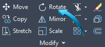
Modification Tools
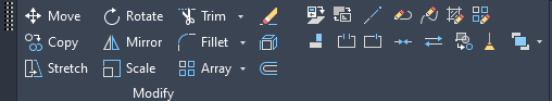
Modification tools change the integrity of objects. Common modification tools are Erase, Move, Rotate, Scale, Stretch, Fillet, Chamfer etc.
Modifications such as Trim, Extend etc, require additional features, such as cutting or boundary edges to perform their task.
In the examples below the Workspace menu is set to Drafting and Annotation and the Home tab is activated.
The Command Line is used to input options for each of the modifications below.
The Dynamic Input fields can also be used to input information related to the modification function. The Dynamic Input fields are useful for specifying angles and spatial distances during the dynamic modification of the selected objects. Dynamic input is activated by left-clicking the customization option shown by 3 small horizontal lines at the lower right of the editor and selecting Dynamic Input from the context menu. When Dynamic Input is activated, it is shown in the Status bar, below.

In all instances of the features below, the keyboard CTL Z, the UUndo command input into the Command line will reverse the most recent command, restoring the objects to their original state in the workspace.
Erase
Drafting & Annotation| Home | Modify | Erase
Objects are selected individually, sequentially, or by selecting them within a window or crossing.
Objects can be removed from the selection using the SHIFT keyboard key.
When the required objects are highlighted, the enter, spacebar or right click mouse button is used to erase the objects.
Example
Method 1 : Draw a series of single objects in the workspace, such as a circle, rectangle and line, shown below. The rectangle, until exploded, is a single object.
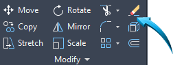
Select Home > Modify > Erase then select each object. The crosshairs/cursor fades indicates the Erase mode by placing a small red cross next to the object being selected. The object is faded out when selected.
Press the spacebar, enter key or right click mouse button to erase the selected objects.
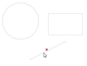
Selecting the objects to erase
Method 2 : With an empty Command Line, left click onto each object to attach grips, shown below. Select Home > Modify > Erase. The objects to which the grips are attached will be erased from the workspace.
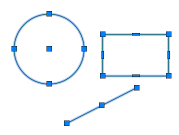
Erasing objects by pre-selecting with grips
Use the keyboard CTRL Z or U to restore the objects to the workspace.
Move

Drafting & Annotation | Home | Modify | Move
This feature relocates the selected objects from a base point to a new destination point. The destination point can be input into the Dynamic Input fields or into the Command Line. The pointing device can also be used to indicate the destination point.
Objects to be moved can be grouped together using a windowLeft-to-Right selection rectangle or crossingRight-to-Left selection rectangle selection.
Object snap modes are useful when relocating objects from a base to a destination point.
Example
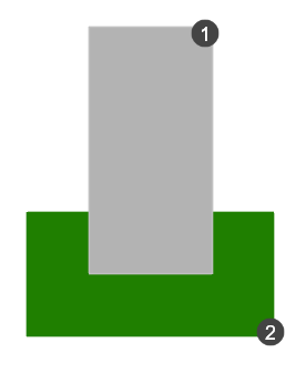
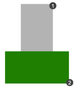
In the example below, the object shown as point 1 will be moved to the destination shown by point 2.
Method 1 :
Select the Move tool from the Home tab or input M enter at the Command line.
Drag a selection window around the left object. When all objects are highlighted, press enter or use the right click mouse button.
At the command> Specify base point or [Displacement] <Displacement> left click at the point shown by the left pointer below to indicate the basepoint.
At the command > Specify the second point >: left click to indicate the point shown by the right arrow in the illustration below.
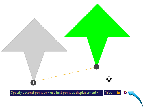
Using the Move tool to relocate object 1 to position shown by point 2. Dynamic Input Fields are used.
Method 2 : With an empty Command Line, left click onto the object/s or use a window selection window to attach grips. Select Home > Modify > Move. The objects to which the grips are attached can be moved in the workspace, using the instructions given in Method 1 above.
Use the keyboard CTRL Z or U to restore the objects to the workspace.
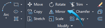
Rotate
Drafting & Annotation | Home | Modify | Move
Keyboard Shortcut : M
Objects can be rotated through any angle by defining a base point and an angle of rotation. The angle of rotation can be input into the Dynamic Input fields or into the Command Line.
Objects to be rotated can be grouped together using a window or crossing selection.
Example
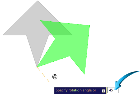
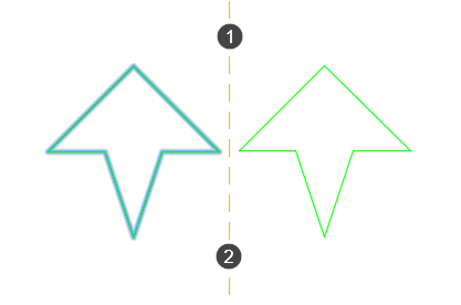
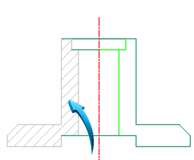
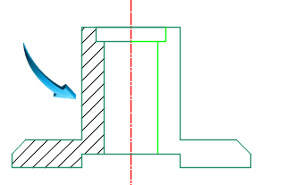
In the example below, the original object is rotated by 45 degrees, indicated by the value in the dynamic input field. The original object is shown faded out and the newly rotated object is shown in green, below.
The Dynamic Input fields are useful for specifying angles during the dynamic rotation of the selected objects. Dynamic input is activated by left-clicking the customization option shown by 3 small horizontal lines at the lower right of the editor and selecting Dynamic Input from the context menu. When Dynamic Input is activated, it is shown in the Status bar, below.
Scale
Drafting & Annotation | Home | Modify | Scale
Objects are scaled around a base point and the increase or decrease value of the scale is input into the Dynamic Input fields or into the Command Line.
When working with a 2D sketch object, or profile, only the X-Y scale factor is required.
Example
In the illustration below, the scale of the object is decreased by .5
Method 1 : Select the Scale tool using Home | Modify | Scale.
Left click onto the objects or drag a selection window around the object/s. When thee selected objects are faded, press enter or use the right click mouse button.
At the command> Specify base point or [Displacement] <Displacement> left click at the point shown by the pointer below to indicate the basepoint.
At the command > Specify the scale factor > input the value into the dynamic input field shown by the pointer below.
The original object is shown faded and the intended object is shown in green.
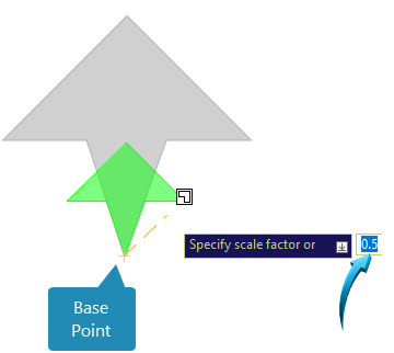
Object X-Y scale decreased by .5
Method 2 : With an empty Command Line, left click onto the object/s or use a window selection window to attach grips. Select Home > Modify > Scale. The objects to which the grips are attached can be scaled in the workspace, using the instructions given in Method 1 above.
Use the keyboard CTRL Z or U to restore the objects to the workspace.
Stretch
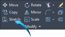
Drafting & Annotation | Home | Modify | Stretch
The Stretch tool stretches or shrinks objects from a base point to a destination point.
A selection crossing is placed around the portion of objects to be stretched.
Example
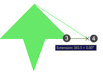
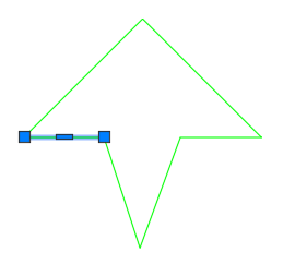
In the example below, the portion to be stretched is selected using a crossingRight-to-Left selection rectangle selection rectangle, shown by points 1 and 2.
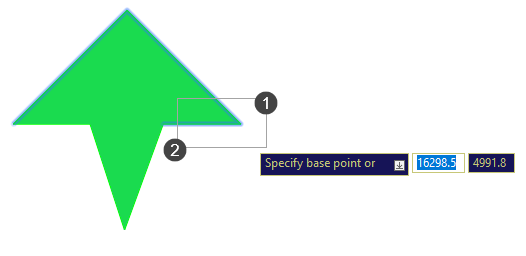
The base point is shown as point 3 below, and the destination point is shown as point 3. For this example, OrthoForces the moved to strictly orthogonal movement. mode is enabled in the Status bar.
Use the keyboard CTRL Z or U to restore the objects to the workspace.
Fillet
Drafting & Annotation | Home | Modify | Fillet
This tool creates a blend to a specified radius on 2 lines or circles.
Example
In the example below a 50x50 rectangle is drawn in the workspace. An arc with a radius of 20 has been inserted at the point shown as 1 and 2 below using the Fillet tool.
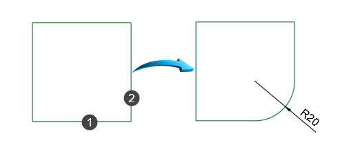
Using Fillet to blend 2 lines
The Fillet tool can be used to create a tangential arc between 2 circles, shown below.
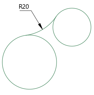
Using Fillet to create a tangential arc
Chamfer
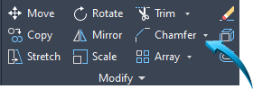
Drafting & Annotation | Home | Modify | Chamfer
This tool creates a beveled edge by defining the x-y distance or angle.
Example
In the illustration below, the Rectangle tool is used to draw a 50x50 4-sided object.
The Chamfer tool with a distance of 15 is used to create a 45° angle between the points on lines 1 and 2.
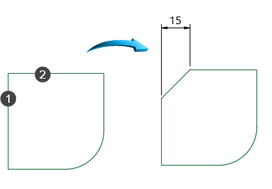
Using Chamfer to create a beveled edge
Extend
Drafting & Annotation | Home | Modify | Extend
This modification tool allows lines to be extended to boundary edges. Multiple objects and boundary edges can be selected at the same time.
The boundary edge is implied, allowing the line to be extended to the logical boundary.
In the example below, line 1 is selected as the line to extend to the boundary edge defined by line 2
The implied extension of line 1 is show, illustrated below right.
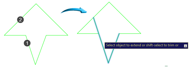
Implied extension of line 1 shown, above right
By selecting line 1, the line is extended to the boundary edge, shown below.
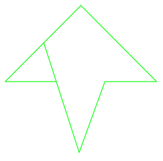
Line 1 extended to the boundary edge defined by line 2
Trim

Drafting & Annotation | Home | Modify | Trim
This tool allows lines to be trimmed by means of another line or circle, defined as a cutting edge.
In the example below, the segment shown by point 1, below left is selected to trim. By selecting this segment, the first logical edge shown by point 2 is assumed as the cutting edge.
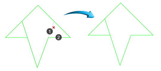
Selecting the segment to trim
Explode

Drafting & Annotation | Home | Modify | Explode
The Explode feature reduces a compound entity to its individual components. For example, a rectangle, when exploded comprises 4 single lines instead of a single polyline.
To restore exploded segments of a polyline sequence, the JoinDrafting & Annotation | Home | Modify | Join tool is used to connect the segments into a polyline sequence.
In the example below, the shape is constructed as a compound entity, usually created from a polyline. This object is selected by left-clicking onto a single entity. In so doing, the entire polyline is selected, shown below.
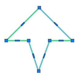
Object shown as single-entity polyline
When exploded, the object is reduced to its constituent parts and selecting any single entity selects only the single line component of the polyline, shown below.
Object shown as single line segments after Explode
Break Tools
Break
Drafting & Annotation | Home | Modify | Break
This modification tool creates one or more break points in a line or arc.
In the example below, the Break tool is used to create a break in the outer circle.

Point 1 indicates first break point; point 2 indicates second break point.
Break at Point
Drafting & Annotation | Home | Modify | Break
This modification tool creates a break point within a line segment without automatically deleting the segment.
In the example below, the line shown selected is a single line segment with the intended break point shown by the pointer at the intersection below.
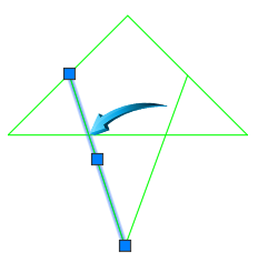
Selecting the line to break at the intersection
By selecting the intersection below left as the break point, the line is divided into 2 separate, intact segments, shown below right. The properties of the separate segments can now be adjusted independently, shown below right.
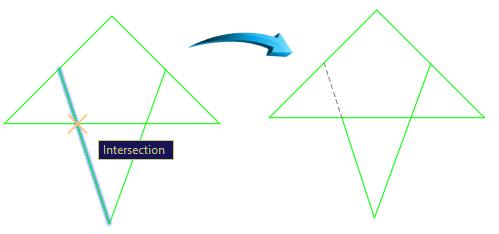
Creating 2 separate, intact segments
Duplication Tools
These duplication tools are part of AutoCAD's modification palette, but their function is to create a duplicate of selected objects.
These tools create duplicates of selected objects without modifying the source object. Examples of Duplication tools are Copy, Mirror, Array etc.
In the examples below the Workspace menu is set to Drafting and Annotation and the Home tab is activated.
Copy
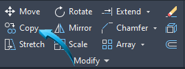
Drafting and Annotation | Home | Modify | Copy
The Copy tool duplicates an object or objects from a specified source point to a destination point. The original objects remain in place.
Spatial coordinates can be input into the Dynamic Input fields or into the Command Line. For example, a distance and angle from the specified base point can be input.
Ortho modeStatus Bar | Ortho or use functon key F8 can be activated to maintain planar integrity when copying the objects.
In the illustration below, the source object shown by point 1 is copied to a position which is 50 to the right of the original position. The Ortho mode is activated for this task.
The distance of 50 and the angle of 0° is input into the Dynamic Input fields, shown below. The original (source) object remains in place.
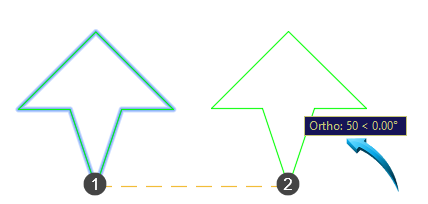
Moving the source object (point 1) 50 to the right (point 2)
Mirror
Drafting and Annotation | Home | Modify | Mirror
The mirror tool duplicates objects symmetrically about a mirror line. The original object can be retained or discarded.
In the illustration below, the object on the left is being mirrored symmetrically across the mirror line shown by points 1 and 2.
Left object is mirrored symmetrically about the mirror line, indicated by points 1 and 2
Offset
Home | Modify | Offset
This tool creates an object which is parallel to another single entity by a defined distance. Lines, polylines, circles and arcs can all be used to create offset features.
In the example below, the outer contour of the shaded shape has been offset by a distance of 5.

Contour of shaded shape offset by 5
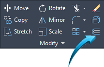
Array
Home | Modify | Array
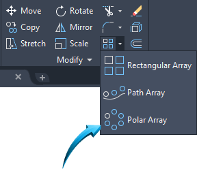
The Array tool allows either the rectangular (cellular) array or the polar array of objects. The original object remains in place.
Rectangular Array
The Rectangular Array feature creates horizontal & vertical duplicates using a specified distance between the rows and columns.
The horizontal duplicates of the rectangular array are referred to as rows.
The vertical duplicates of the rectangular array are referred to as columns.
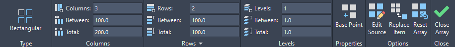
After the objects are arrayed, the properties of the arrayed pattern can be modified using the options shown below.
Take Note
This is a context-sensitive menu and responds to the specific array created. In the example below, modifications can be done on a Rectangular Array.
Example
The arrayed pattern is created from the lower left corner and there are 3 Columns and 2 Rows with a cellular distance of 100.
In the example below, the source object is shown in the lower left corner.
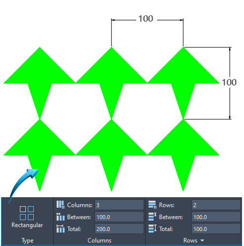
3 Column, 2 Row array
To modify the properties of the Array, select the array pattern using a selection window, then update the properties in the menu edit fields.
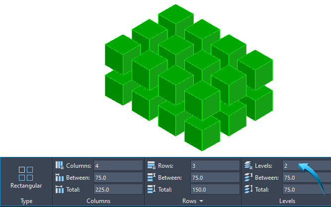
Using Levels
When using a Rectangular Array, a number of levels can be created in addition to the columns and rows. This creates a 3-dimensional array, similar to the illustration in the example below.
Example
In the example below, the 3D Basics menu is used.
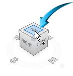
An isometric view is selected in the ViewCube, similar to the illustration below.
A Box is drawn to measurements 50x50x50.
The Rectangular Array tool is selected and the newly drawn box is selected as the source object. The information shown below is input into the menu data fields to produce a 3-dimensional array by creating 2 levels.
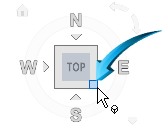
To return the view in the workspace to Plan, click Top in the ViewCube, shown below.
Polar Array
The Polar Array tool copies and rotates objects in a circular pattern by defining a center and an angle of rotation.
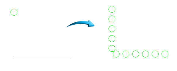
In the example below, the source object shown left is copied and arrayed 6 times about the center, shown by the pointer in the illustration left.
The source object remains in place, but is rotated as part of the arrayed pattern, shown below right.
Example
In the example below, 4 items are arrayed using the top shape as the source object. The pattern is created by arraying the top shape in a clockwise direction. The base point of the array is shown in the center. The number of items is 4 and the total angle of the array is 360°

4 item polar array thru 360°
To modify the properties of the Array, select the array pattern using a selection window, then update the properties in the menu edit fields.
Path Array
This allows an object to be arrayed equidistantly along an object defined as a path curve.
In the example below, the top circle is arrayed along the path defined by the polyline.
The distance between the arrayed objects only is required.
Using Path Array
Objects can be arrayed along a path lying in any plane provided the source object is in a perpendicular plane to the path object, shown below.

Using Path Array in an isometric view
Edit Array
Home | Modify | Edit Array
Objects arrayed in either a rectangular or polar pattern can be modified using the Edit Array tool. The configuration of the array can be modified, as well as the shape of the source object.
When the source object is modified, these changes are cascaded to the arrayed objects.
Example
In the example below, the shape of the source object shown by the pointer will be adjusted.
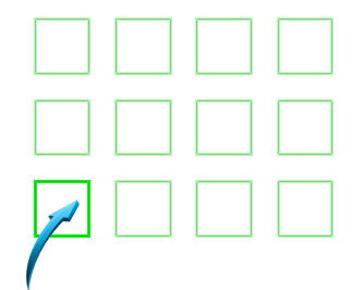
Selecting the source object of the array
The Edit Array command is used to select the entire array, then the Source option is selected.
Changes made to the source object will be cascaded to the remaining arrayed objects, shown below.
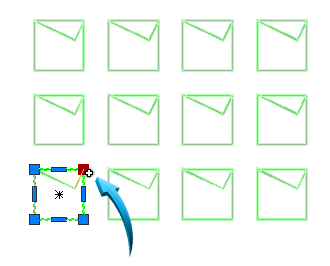
Changing the shape of the source object updates all arrayed objects
Draw Order
Drafting & Annotation | Home | Modify | Draw Order
Objects can be manipulated using a visual 'stacking' system whereby objects can take priority or precedence over other objects in the same plane.
When objects occupy the same plane, it is difficult to control their appearance when they are viewed on the screen and when printed. In the case of hatching, the hatch pattern creates its own border which frequently will occupy the same plane as the profile of the objects.
Example
In the illustration below, object 1 takes precedence over item 2 in that its outline and fill occupy a plane that takes priority over item 2.
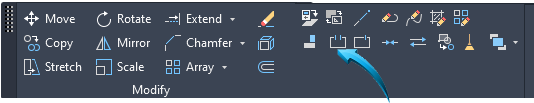
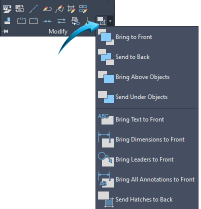
By selecting the 'Send to Back' option and selecting item 2, the result shown below is achieved.
Send Hatches to Back
In the example below, the hatch pattern is inserted into the area shown by the pointer. At present, the border of the hatch pattern takes precedence over the profile of the sketch.
Hatch pattern boundary takes precedence over sketch boundary
Example
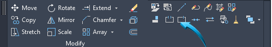
The draw order of the hatch pattern is moved such that it is behind the sketch profile using the Send Hatches to Back option to produce the result shown below.
In this example, the profile of the sketch now takes precedence over the hatched area.
Hatch boundary moved behind sketch boundary
